UNIT-IV Input output organization
INPUT OUTPUT ORGANIZATION
What are Peripheral Devices?
Peripheral devices are those devices that are linked either internally or externally to a computer. These devices are commonly used to transfer data. The most common processes that are carried out in a computer are entering data and displaying processed data. Several devices can be used to receive data and display processed data. The devices used to perform these functions are called peripherals or I/O devices.
Peripherals read information from or write in the memory unit on receiving a command from the CPU. They are considered to be a part of the total computer system. As they require a conversion of signal values, these devices can be referred to as electromechanical and electromagnetic devices. The most common peripherals are a printer, scanner, keyboard, mouse, tape device, microphone, and external modem that are externally connected to the computer.
The following are some of the commonly used peripherals −
Keyboard
The keyboard is the most commonly used input device. It is used to provide commands to the computer. The commands are usually in the form of text. The keyboard consists of many keys such as function keys, numeric keypad, character keys, and various symbols.
Monitor
The most commonly used output device is the monitor. A cable connects the monitor to the video adapters in the computer’s motherboard. These video adapters convert the electrical signals to the text and images that are displayed. The images on the monitor are made of thousands of pixels. The cursor is the characteristic feature of display devices. It marks the position on the screen where the next character will be inserted.
Printer
Printers provide a permanent record of computer data or text on paper. We can classify printers as impact and non-impact printers. Impact printers print characters due to the physical contact of the print head with the paper. In non-impact printers, there is no physical contact.
Magnetic Tape
Magnetic tapes are used in most companies to store data files. Magnetic tapes use a read-write mechanism. The read-write mechanism refers to writing data on or reading data from a magnetic tape. The tapes sequentially store the data manner. In this sequential processing, the computer must begin searching at the beginning and check each record until the desired data is available.
Magnetic tape is the cheapest medium for storage because it can store a large number of binary digits, bytes, or frames on every inch of the tape. The advantages of using magnetic tape include unlimited storage, low cost, high data density, rapid transfer rate, portability, and ease of use.
Magnetic Disk
There is another medium for storing data is magnetic disks. Magnetic disks have high-speed rotational surfaces coated with magnetic material. A read-write mechanism is used to achieve access to write on or read from the magnetic disk. Magnetic disks are generally used for the volume storage of programs and information.
There are some peripheral devices found in computer systems including digital incremental plotters, optical and magnetic readers, analog to digital converters, and several data acquisition equipment.
I/O Interface in Computer Architecture?
The I/O interface supports a method by which data is transferred between internal storage and external I/O devices. All the peripherals connected to a computer require special communication connections for interfacing them with the CPU.
I/O Bus and Interface Modules
The I/O bus is the route used for peripheral devices to interact with the computer processor. A typical connection of the I/O bus to I/O devices is shown in the figure.
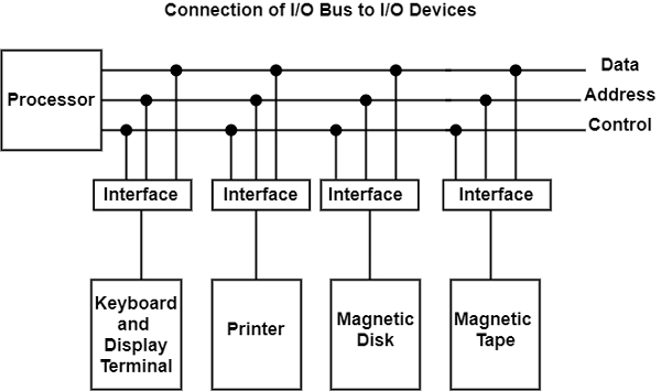
The I/O bus includes data lines, address lines, and control lines. In any general-purpose computer, the magnetic disk, printer, and keyboard, and display terminal are commonly employed. Each peripheral unit has an interface unit associated with it. Each interface decodes the control and address received from the I/O bus.
It can describe the address and control received from the peripheral and supports signals for the peripheral controller. It also conducts the transfer of information between peripheral and processor and also integrates the data flow.
The I/O bus is linked to all peripheral interfaces from the processor. The processor locates a device address on the address line to interact with a specific device. Each interface contains an address decoder attached to the I/O bus that monitors the address lines.
When the address is recognized by the interface, it activates the direction between the bus lines and the device that it controls. The interface disables the peripherals whose address does not equivalent to the address in the bus.
An interface receives any of the following four commands −
- Control − A command control is given to activate the peripheral and to inform its next task. This control command depends on the peripheral, and each peripheral receives its sequence of control commands, depending on its mode of operation.
- Status − A status command can test multiple test conditions in the interface and the peripheral.
- Data Output − A data output command creates the interface counter to the command by sending data from the bus to one of its registers.
- Data Input − The data input command is opposite to the data output command. In data input, the interface gets an element of data from the peripheral and places it in its buffer register.
Asynchronous Data Transfer in Computer Organization
The internal operations in an individual unit of a digital system are synchronized using clock pulse. It means clock pulse is given to all registers within a unit. And all data transfer among internal registers occurs simultaneously during the occurrence of the clock pulse. Now, suppose any two units of a digital system are designed independently, such as CPU and I/O interface.
If the registers in the I/O interface share a common clock with CPU registers, then transfer between the two units is said to be synchronous. But in most cases, the internal timing in each unit is independent of each other, so each uses its private clock for its internal registers. In this case, the two units are said to be asynchronous to each other, and if data transfer occurs between them, this data transfer is called Asynchronous Data Transfer.
But, the Asynchronous Data Transfer between two independent units requires that control signals be transmitted between the communicating units so that the time can be indicated at which they send data. These two methods can achieve this asynchronous way of data transfer:
- Strobe control: A strobe pulse is supplied by one unit to indicate to the other unit when the transfer has to occur.
- Handshaking: This method is commonly used to accompany each data item being transferred with a control signal that indicates data in the bus. The unit receiving the data item responds with another signal to acknowledge receipt of the data.
The strobe pulse and handshaking method of asynchronous data transfer is not restricted to I/O transfer. They are used extensively on numerous occasions requiring the transfer of data between two independent units. So, here we consider the transmitting unit as a source and receiving unit as a destination.
For example, the CPU is the source during output or write transfer and the destination unit during input or read transfer.
Therefore, the control sequence during an asynchronous transfer depends on whether the transfer is initiated by the source or by the destination.
So, while discussing each data transfer method asynchronously, you can see the control sequence in both terms when it is initiated by source or by destination. In this way, each data transfer method can be further divided into parts, source initiated and destination initiated.
Asynchronous Data Transfer Methods
The asynchronous data transfer between two independent units requires that control signals be transmitted between the communicating units to indicate when they send the data. Thus, the two methods can achieve the asynchronous way of data transfer.
1. Strobe Control Method
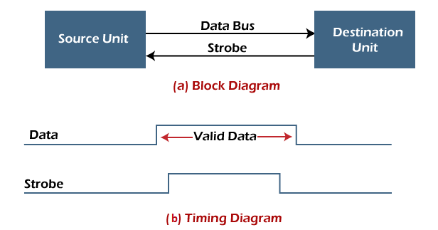
The Strobe Control method of asynchronous data transfer employs a single control line to time each transfer. This control line is also known as a strobe, and it may be achieved either by source or destination, depending on which initiate the transfer.
- Source initiated strobe: In the below block diagram, you can see that strobe is initiated by source, and as shown in the timing diagram, the source unit first places the data on the data bus.

After a brief delay to ensure that the data resolve to a stable value, the source activates a strobe pulse. The information on the data bus and strobe control signal remains in the active state for a sufficient time to allow the destination unit to receive the data.
The destination unit uses a falling edge of strobe control to transfer the contents of a data bus to one of its internal registers. The source removes the data from the data bus after it disables its strobe pulse. Thus, new valid data will be available only after the strobe is enabled again.
In this case, the strobe may be a memory-write control signal from the CPU to a memory unit. The CPU places the word on the data bus and informs the memory unit, which is the destination. - Destination initiated strobe: In the below block diagram, you see that the strobe initiated by destination, and in the timing diagram, the destination unit first activates the strobe pulse, informing the source to provide the data.
The source unit responds by placing the requested binary information on the data bus. The data must be valid and remain on the bus long enough for the destination unit to accept it.
The falling edge of the strobe pulse can use again to trigger a destination register. The destination unit then disables the strobe. Finally, and source removes the data from the data bus after a determined time interval.
In this case, the strobe may be a memory read control from the CPU to a memory unit. The CPU initiates the read operation to inform the memory, which is a source unit, to place the selected word into the data bus.
2. Handshaking Method
The strobe method has the disadvantage that the source unit that initiates the transfer has no way of knowing whether the destination has received the data that was placed in the bus. Similarly, a destination unit that initiates the transfer has no way of knowing whether the source unit has placed data on the bus.
So this problem is solved by the handshaking method. The handshaking method introduces a second control signal line that replays the unit that initiates the transfer.
In this method, one control line is in the same direction as the data flow in the bus from the source to the destination. The source unit uses it to inform the destination unit whether there are valid data in the bus.
The other control line is in the other direction from the destination to the source. This is because the destination unit uses it to inform the source whether it can accept data. And in it also, the sequence of control depends on the unit that initiates the transfer. So it means the sequence of control depends on whether the transfer is initiated by source and destination.
- Source initiated handshaking: In the below block diagram, you can see that two handshaking lines are "data valid", which is generated by the source unit, and "data accepted", generated by the destination unit.
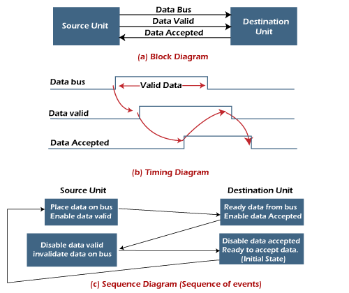
The timing diagram shows the timing relationship of the exchange of signals between the two units. The source initiates a transfer by placing data on the bus and enabling its data valid signal. The destination unit then activates the data accepted signal after it accepts the data from the bus.
The source unit then disables its valid data signal, which invalidates the data on the bus.
After this, the destination unit disables its data accepted signal, and the system goes into its initial state. The source unit does not send the next data item until after the destination unit shows readiness to accept new data by disabling the data accepted signal.
This sequence of events described in its sequence diagram, which shows the above sequence in which the system is present at any given time. - Destination initiated handshaking: In the below block diagram, you see that the two handshaking lines are "data valid", generated by the source unit, and "ready for data" generated by the destination unit.
Note that the name of signal data accepted generated by the destination unit has been changed to ready for data to reflect its new meaning.
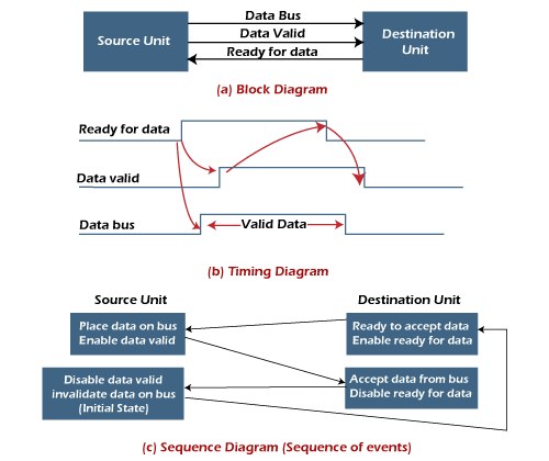
The destination transfer is initiated, so the source unit does not place data on the data bus until it receives a ready data signal from the destination unit. After that, the handshaking process is the same as that of the source initiated.
The sequence of events is shown in its sequence diagram, and the timing relationship between signals is shown in its timing diagram. Therefore, the sequence of events in both cases would be identical.
The asynchronous data transfer between two independent units requires that control signals be transmitted between the communicating units to indicate when they send the data. Thus, the two methods can achieve the asynchronous way of data transfer.
1. Strobe Control Method
The Strobe Control method of asynchronous data transfer employs a single control line to time each transfer. This control line is also known as a strobe, and it may be achieved either by source or destination, depending on which initiate the transfer.
- Source initiated strobe: In the below block diagram, you can see that strobe is initiated by source, and as shown in the timing diagram, the source unit first places the data on the data bus.
After a brief delay to ensure that the data resolve to a stable value, the source activates a strobe pulse. The information on the data bus and strobe control signal remains in the active state for a sufficient time to allow the destination unit to receive the data.
The destination unit uses a falling edge of strobe control to transfer the contents of a data bus to one of its internal registers. The source removes the data from the data bus after it disables its strobe pulse. Thus, new valid data will be available only after the strobe is enabled again.
In this case, the strobe may be a memory-write control signal from the CPU to a memory unit. The CPU places the word on the data bus and informs the memory unit, which is the destination. - Destination initiated strobe: In the below block diagram, you see that the strobe initiated by destination, and in the timing diagram, the destination unit first activates the strobe pulse, informing the source to provide the data.
The source unit responds by placing the requested binary information on the data bus. The data must be valid and remain on the bus long enough for the destination unit to accept it.
The falling edge of the strobe pulse can use again to trigger a destination register. The destination unit then disables the strobe. Finally, and source removes the data from the data bus after a determined time interval.
In this case, the strobe may be a memory read control from the CPU to a memory unit. The CPU initiates the read operation to inform the memory, which is a source unit, to place the selected word into the data bus.
2. Handshaking Method
The strobe method has the disadvantage that the source unit that initiates the transfer has no way of knowing whether the destination has received the data that was placed in the bus. Similarly, a destination unit that initiates the transfer has no way of knowing whether the source unit has placed data on the bus.
So this problem is solved by the handshaking method. The handshaking method introduces a second control signal line that replays the unit that initiates the transfer.
In this method, one control line is in the same direction as the data flow in the bus from the source to the destination. The source unit uses it to inform the destination unit whether there are valid data in the bus.
The other control line is in the other direction from the destination to the source. This is because the destination unit uses it to inform the source whether it can accept data. And in it also, the sequence of control depends on the unit that initiates the transfer. So it means the sequence of control depends on whether the transfer is initiated by source and destination.
- Source initiated handshaking: In the below block diagram, you can see that two handshaking lines are "data valid", which is generated by the source unit, and "data accepted", generated by the destination unit.
The timing diagram shows the timing relationship of the exchange of signals between the two units. The source initiates a transfer by placing data on the bus and enabling its data valid signal. The destination unit then activates the data accepted signal after it accepts the data from the bus.
The source unit then disables its valid data signal, which invalidates the data on the bus.
After this, the destination unit disables its data accepted signal, and the system goes into its initial state. The source unit does not send the next data item until after the destination unit shows readiness to accept new data by disabling the data accepted signal.
This sequence of events described in its sequence diagram, which shows the above sequence in which the system is present at any given time. - Destination initiated handshaking: In the below block diagram, you see that the two handshaking lines are "data valid", generated by the source unit, and "ready for data" generated by the destination unit.
Note that the name of signal data accepted generated by the destination unit has been changed to ready for data to reflect its new meaning.
The destination transfer is initiated, so the source unit does not place data on the data bus until it receives a ready data signal from the destination unit. After that, the handshaking process is the same as that of the source initiated.
The sequence of events is shown in its sequence diagram, and the timing relationship between signals is shown in its timing diagram. Therefore, the sequence of events in both cases would be identical.
Advantages of Asynchronous Data Transfer
Asynchronous Data Transfer in computer organization has the following advantages, such as:
- It is more flexible, and devices can exchange information at their own pace. In addition, individual data characters can complete themselves so that even if one packet is corrupted, its predecessors and successors will not be affected.
- It does not require complex processes by the receiving device. Furthermore, it means that inconsistency in data transfer does not result in a big crisis since the device can keep up with the data stream. It also makes asynchronous transfers suitable for applications where character data is generated irregularly.
Disadvantages of Asynchronous Data Transfer
There are also some disadvantages of using asynchronous data for transfer in computer organization, such as:
- The success of these transmissions depends on the start bits and their recognition. Unfortunately, this can be easily susceptible to line interference, causing these bits to be corrupted or distorted.
- A large portion of the transmitted data is used to control and identify header bits and thus carries no helpful information related to the transmitted data. This invariably means that more data packets need to be sent.
Modes of Transfer
Introduction
The following blog discusses one of the important topics involved in Computer Organization and Architecture. The method used for transferring information between external I/O devices and internal storage is known as the I/O interface. We use special communication links to interface the CPU with the peripherals connected to any computer system. We use these communication links to resolve the differences between the CPU and peripheral.
The Input-Output Interface is an essential component in computer systems. It enables communication between the CPU and various external devices. These external devices are peripherals like keyboards, monitors, printers, and storage devices such as hard drives, network interfaces, etc.
Modes of Transfer
We store the binary information received through an external device in the memory unit. The information transferred from the CPU to external devices originates from the memory unit. Although the CPU processes the data, the target and source are always the memory unit. We can transfer this information using three different modes of transfer.
- Programmed I/O
- Interrupt- initiated I/O
- Direct memory access( DMA)
We will see each of them in detail in the upcoming sections.
1. Programmed I/O
Programmed I/O uses the I/O instructions written in the computer program. The instructions in the program initiate every data item transfer. Usually, the data transfer is from a memory and CPU register. This case requires constant monitoring by the peripheral device's CPU.
Advantages:
- Programmed I/O is simple to implement.
- It requires very little hardware support.
- CPU checks status bits periodically.
Disadvantages:
- The processor has to wait for a long time for the I/O module to be ready for either transmission or reception of data.
- The performance of the entire system is severely degraded.
2. Interrupt-initiated I/O
In the above section, we saw that the CPU is kept busy unnecessarily. We can avoid this situation by using an interrupt-driven method for data transfer. The interrupt facilities and special commands inform the interface for issuing an interrupt request signal as soon as the data is available from any device. In the meantime, the CPU can execute other programs, and the interface will keep monitoring the i/O device. Whenever it determines that the device is ready for transferring data interface initiates an interrupt request signal to the CPU. As soon as the CPU detects an external interrupt signal, it stops the program it was already executing, branches to the service program to process the I/O transfer, and returns to the program it was initially running.
Working of CPU in terms of interrupts:
- CPU issues read command.
- It starts executing other programs.
- Check for interruptions at the end of each instruction cycle.
- On interruptions:-
- Process interrupt by fetching data and storing it.
- See operation system notes.
- Starts working on the program it was executing.
Advantages:
- It is faster and more efficient than Programmed I/O.
- It requires very little hardware support.
- CPU does not check status bits periodically.
Disadvantages:
- It can be tricky to implement if using a low-level language.
- It can be tough to get various pieces of work well together.
- The hardware manufacturer / OS maker usually implements it, e.g., Microsoft.
3. Direct Memory Access (DMA)
The data transfer between any fast storage media like a memory unit and a magnetic disk gets limited with the speed of the CPU. Thus it will be best to allow the peripherals to directly communicate with the storage using the memory buses by removing the intervention of the CPU. This mode of transfer of data technique is known as Direct Memory Access (DMA). During Direct Memory Access, the CPU is idle and has no control over the memory buses. The DMA controller takes over the buses and directly manages data transfer between the memory unit and I/O devices.
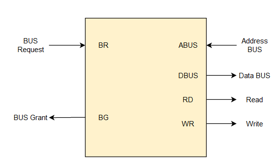
CPU Bus Signal for DMA transfer
Bus Request - We use bus requests in the DMA controller to ask the CPU to relinquish the control buses.
Bus Grant - CPU activates bus grant to inform the DMA controller that DMA can take control of the control buses. Once the control is taken, it can transfer data in many ways.
Types of DMA transfer using DMA controller:
- Burst Transfer: In this transfer, DMA will return the bus control after the complete data transfer. A register is used as a byte count, which decrements for every byte transfer, and once it becomes zero, the DMA Controller will release the control bus. When the DMA Controller operates in burst mode, the CPU is halted for the duration of the data transfer.
- Cyclic Stealing: It is an alternative method for data transfer in which the DMA controller will transfer one word at a time. After that, it will return the control of the buses to the CPU. The CPU operation is only delayed for one memory cycle to allow the data transfer to “steal” one memory cycle.
Advantages
- It is faster in data transfer without the involvement of the CPU.
- It improves overall system performance and reduces CPU workload.
- It deals with large data transfers, such as multimedia and files.
Disadvantages
- It is costly and complex hardware.
- It has limited control over the data transfer process.
- Risk of data conflicts between CPU and DMA.
Comments
Post a Comment